Past Projects
Current Projects | Past Projects | Videos

We are interested in the design and control of autonomous micro aerial vehicles in unknown, cluttered environments. The applications for such MAVs range from search-and-rescue, security, surveillance, mapping, and remote sensing. Traditional vertical take-off and landing micro aerial vehicles are generally underactuated, i.e., equipped with fewer actuators than degrees-of-freedom. As a consequence, they possess a limited mobility because of their inherent underactuation (e.g., quadorotor helicopters can neither translate laterally with a zero attitude nor hover at a spot with a nonzero attitude). We would like a MAV to hover in place with any body orientation and be able to translate with a zero attitude. Additionally, we want to be able to arbitrarily orient a sensor or gripper attached to the MAV body during flight. In order to overcome the limitations of conventional MAVs and realize fully controllable MAVs, we are investigating new fully and over-actuated MAV configurations and actuation techniques.
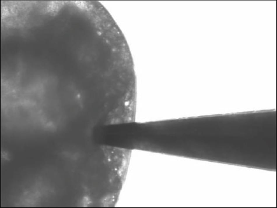
Automation technologies can be used to support research in biological cell manipulation and characterization. Physical characterization of cells can be performed by indenting a cell membrane a fixed amount and recording the corresponding force data. The multi-scale manipulation system at the MSRAL has been outfitted for these types of studies. This research requires the attachment of a pipette with suction capabilities to the manual manipulator along with the integration of a force sensing device to the active manipulator. A study has been conducted on golden whitefish egg cells, which have an outside diameter of 2-3 mm and manipulation and puncture forces on the order of milli-Newtons. Therefore, an off-the-shelf 10g load cell is used for force sensing. Cell indentations of various amounts were produced on the cell by actuating the active manipulator and corresponding forces recorded. This type of force-deflection data can be used to determine stiffness metrics for a particular cell and is useful when comparing different types of cells. Cell relaxation has been observed from examining the force values over time that the cell exerts on the manipulation tool while the cell is indented. This relaxation is modeled with a spring-damper system to further characterize the behavior of the cell. In addition, the effects of salinity and diameter of the stiffness of the cell have also been studied.

The goal of this project is to develop a new framework to control teams of mobile robots, cooperating in a beamforming fashion, to transmit information between multiple source-destination pairs, while meeting quality-of-service constraints and consuming minimum power. The approach of this project ensures robust communications and longevity in challenging environments, arising during the transmission of high-rate data, such as video or images, or in environments where there is no line-of-sight. It also allows significant performance gains compared to static systems that do not consider mobility. The intellectual merit of this research lies in the development of a cyber-physical system of mobile beamformers, where the physical space of robot trajectories and velocities constitutes an input to the cyber space of wireless communications, and vise versa. This is a collaborative project with Duke (Lead) and Rutgers. Our project tasks are related to the physical platform design, deployment and validation.
The goal of this research thrust is to create a flexible, micro-scale additive manufacturing platform utilizing a team of untethered micro-scale robots and modular, multifunctional building blocks to create smart micro-devices and structures. Externally applied magnetic fields are commonly used for the power and actuation of individual magnetic mobile microrobots. However, in order to achieve different behaviors from individual robots within a team of microrobots, there must be either significant variation in their design or in the magnetic control signals applied to each microrobot. We are currently working on a novel approach to create a specialized magnetic potential field generating substrates using planar microcoils and the related control methodology to enable truly independent control of multiple mobile microrobots.

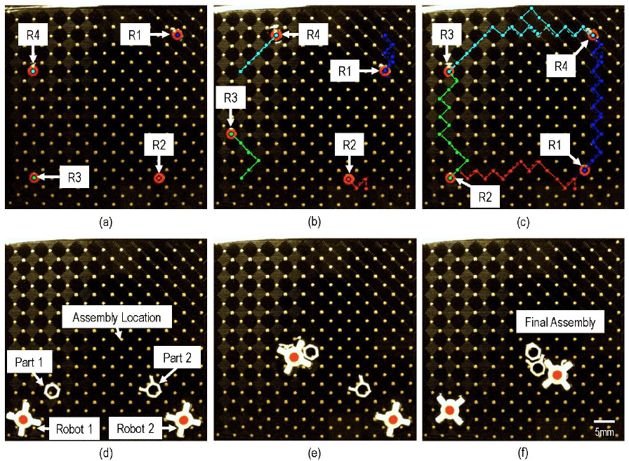
Complicated tasks may be too difficult for a single robot to accomplish alone or a team of homogenous robots to dexterously accomplish. Thus, coordination of a heterogeneous team of robots can allow the completion of a complicated task that a team of only one sub-group would be incapable of achieving. For example, aerial robots exhibit several advantages over ground robots, including the ability to maneuver through complex three-dimensional environments and gather data from vantages inaccessible to ground robots. However, aerial robots also have several limitations that reduce their applicability, such as the need for wireless communication and a limited onboard power supply that restricts the platform’s payload capacity and flying time. On the other hand, ground robots can carry large payloads and requisite computing power and communications hardware. In this project, we are investigating how heterogeneous teams of ground and aerial robots can work together to in efficient ways to accomplish various tasks that would not be possible with a single or homogenous team of robots.

We have designed a micro-scale Magnetic Asymmetric thin film Bimorph (µMAB) microrobot. Magnetostrictive bending, made from a magnetic film bonded to a nonmagnetic substrate, occurs when the film is magnetized by an applied field. A magnetostrictive stress is produced in the film. Bending occurs if one end of the two layer structures is clamped. Further, if the deflected end is in contact with some ground or face, a blocking force is produced which is able to provide mechanical work through the friction force it causes. Legs with different geometry dimensions and different contact line/areas are able to lead to different blocking forces and then friction forces. Making use of the friction difference along the contact face between the robot and the supporting substrate can push or pull the robot mass. If the robot is on the substrate and the external magnetic field is static and constant, the robot legs will remain bent; if the magnetic field is a pulsing signal on and off, the legs will perform bending and straightening, which means a walking/crawling motion will result. Further, when the surrounding magnetic field is a high frequency pulsing signal, for example, with the natural frequency of the robot, the robot would be expected to perform very fast walking and/or running motions. The direction control can be readily realized by changing the direction of magnetic field to align the magnetic body.

Manipulation and puncture forces on biological cells with diameters of a few hundred microns are on the order of micro-Newtons (µN’s). Manipulation forces as a result of pushing manipulations on micro- and meso-scale parts are also on the order of micro-Newtons. There are no low-cost, reliable, off-the-shelf, commercially available force sensors to measure forces at this scale. Therefore, we have developed force sensors to resolve forces at this scale to use for these types of microrobotic manipulation tasks. It is desired to have as few as possible extra parts cluttering the workspace and interfering with the manipulation tool. In order to take advantage of the pre-existing components of a typical manipulation system, a compliant mechanism, computer vision based, force sensing device has been developed. From observing the deformation of a calibrated structure as it interacts with an object that it is manipulating, the actual manipulation force can be extracted. The force sensor is directly mounted to the micromanipulator at one end, while the other end is used to manipulate the parts. The device is designed with fiducial markers that can be tracked in two dimensions in the images from the CCD camera, providing two dimensional (in the XY-plane) µN level force sensing. Thus, only the tip of the device is required to be present in the field of view of the microscope. Due to the image size and microscope objective, the desired resolution for the force sensor is = 0.25 µN/pixel. This corresponds to a maximum stiffness in each direction of 0.0475 N/m. The design topology is inspired by traditional MEMS suspension mechanisms found in accelerometers and resonators made from silicon wafers. However, silicon wafers are much too stiff to produce a device at the desired stiffness level in the workspace constraints of the system as well as with sufficient out-of-plane stiffness. Therefore, the force sensors are made out of a much more compliant polydimethylsiloxane (PDMS) material. The manufacturing process consists of photolithography with a thick, negative photoresist to create a photoresist mold on a silicon wafer substrate. The PDMS is then poured in the mold, allowed to cure, and then released producing the finished device.
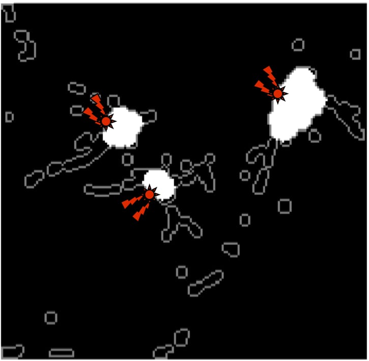
This project is on automating the phototransfection process on neuron and fibroblast cells. Phototransfection is presently done manually in a very tedious manner: First, the cell of interest needs to be identified in the microscope FOV and location recorded. Then an appropriate location of where to administer a laser beam on the cell body needs to be determined. Applying the laser to the wrong location can damage the cell. The laser beam creates a hole in the cell membrane where donor mRNA can be inserted to the cell from a pipette, completing the process. A framework for fully automating this procedure has been designed and proof-of-concept implementation achieved. Computer vision techniques are used to identify the cell of interest in the FOV and determine target locations for the laser beam. A control program takes this information and coordinates movements of the computer controlled XY stage, translating the coordinates of the laser target location to a predefined, fixed, laser firing location. A 20X improvement was shown to be possible with this implementation with room for improvement to greater than 80X.